Overview:

SR26 4WD Actuation Dog Clutch

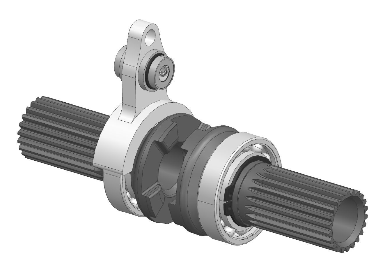
I designed and analyzed the 4WD engagement/disengagement dog clutch for our car. In addition to the design of the actual clutch components, I also developed a new packaging architecture that allowed frame weight to be locally reduced by ~10% and massively increased manufacturability. This is the first dog clutch designed in our team’s history that has functioned continuously with no issues through all of testing and competition.

SR26 4WD Actuation Dog Clutch

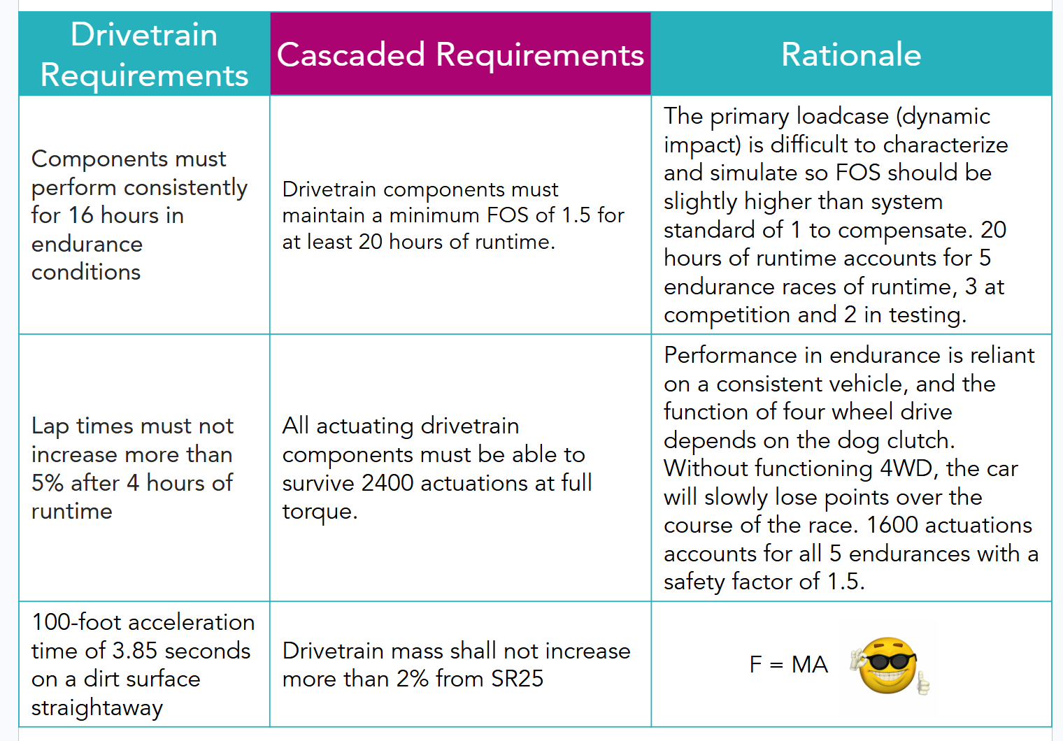
Before I began design, I derived the part level requirements for the dog clutch system from the overall drivetrain requirements.

Drivetrain Requirements, Cascaded Requirements, and Rationale
In previous years, reliability with four-wheel drive engagement and disengagement has been a massive issue that has lost the team significant points in endurance, the largest points scoring event. Reliability and efficient mass usage were the priorities for the redesign of the system, which is reflected in the requirements.

After deriving my requirements, I spoke to the previous designer and reflected on issues and what worked. I came up with this list of issues:

Consistent engagement and reliability

  • Only ran consistently for an entire endurance race one time without failure
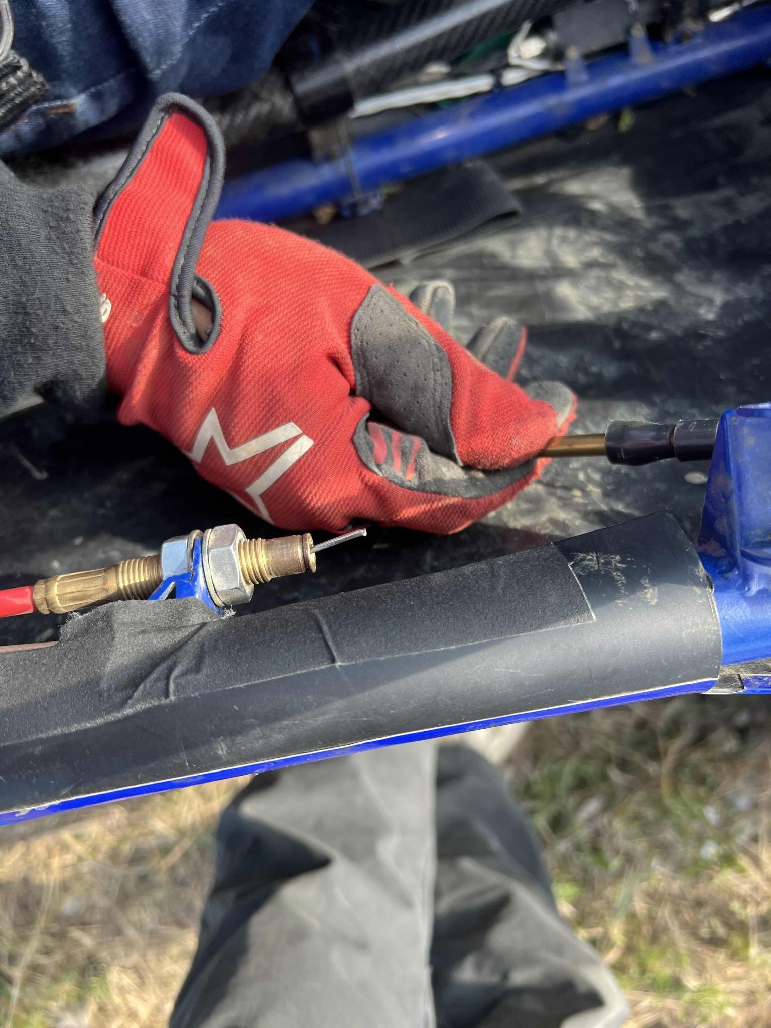
  • Often difficult to engage consistently and repetitively without excessive force, which resulted in the push pull cable breaking during ⅔ competitions.
Snapped push-pull cable after Maryland endurance

Wear and tear on the dog gears

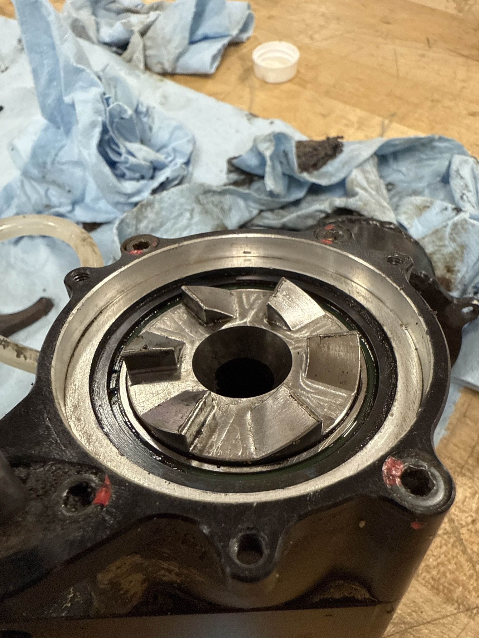
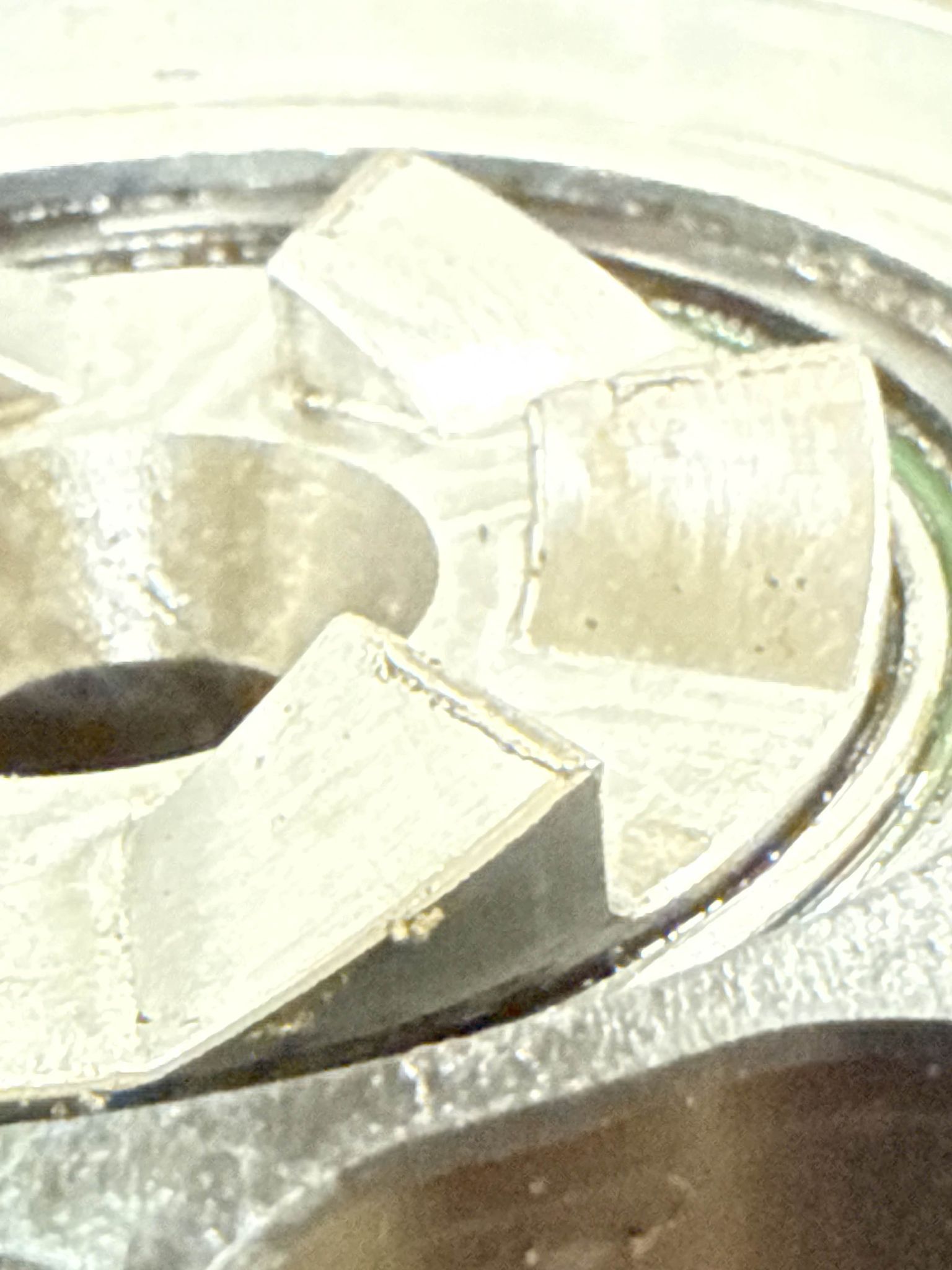
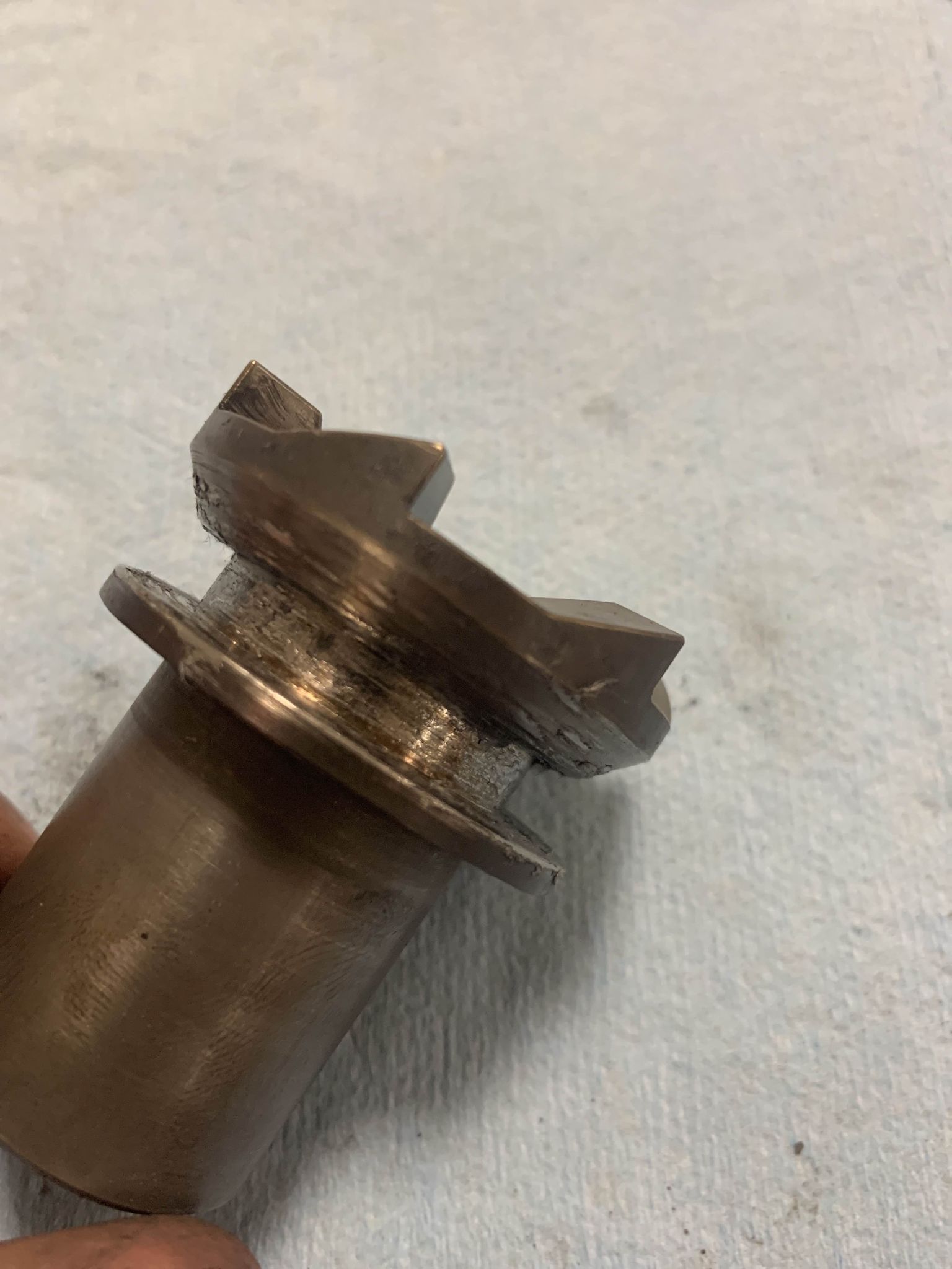
  • Because of the engagement issues, the gears would often break contact and collide repeatedly because they were not fully engaged or disengaged.
locally yielded dog teeth from repeated impacts locally yielded dog teeth from repeated impacts
locally yielded dog teeth from repeated impacts

Issues with throwout fork design

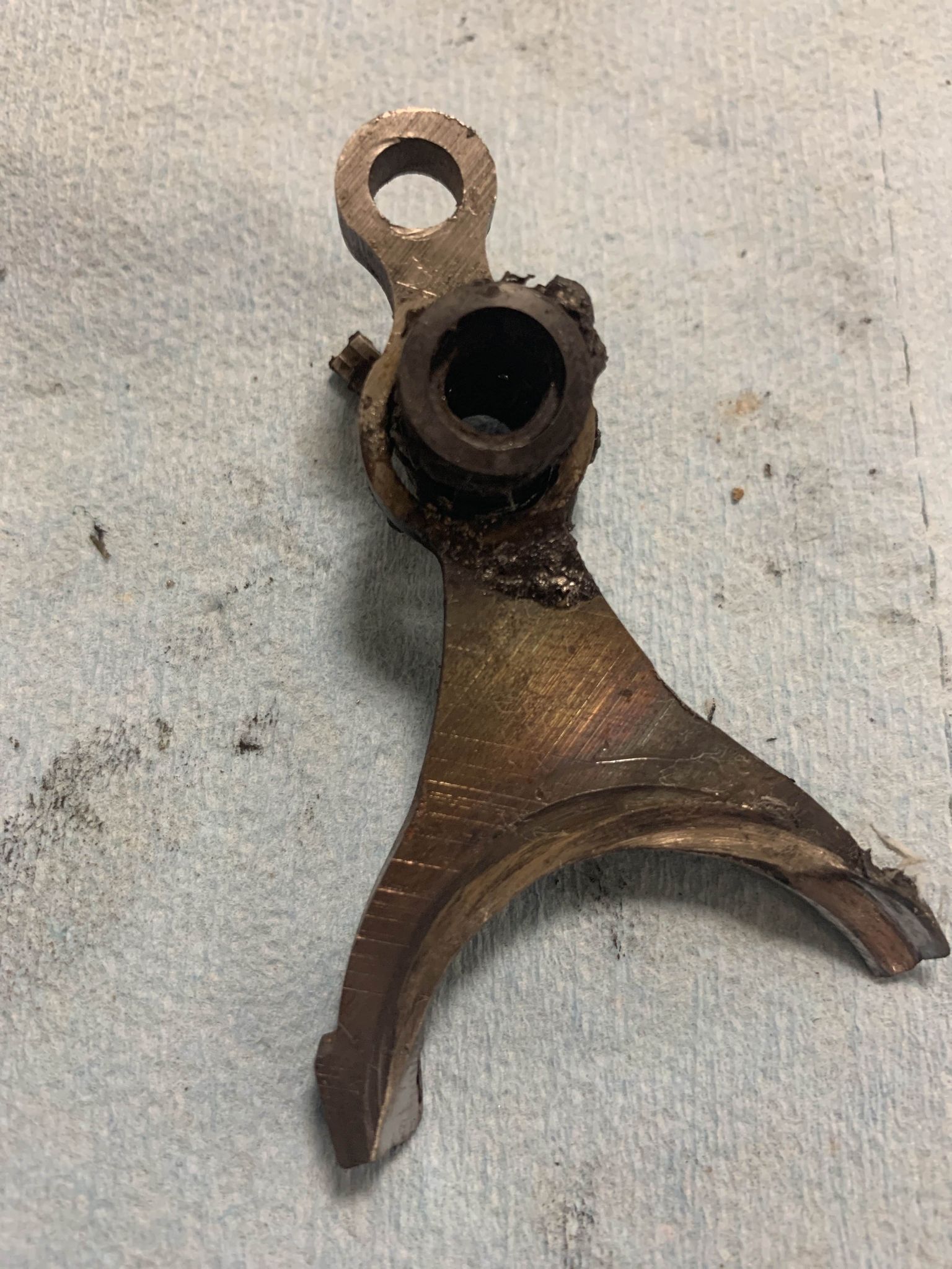
  • Because of the way that the throwout fork interfaced with the dog gears, there was a large amount of friction and heat generation while racing. They were also largely unoptimized for bending loads, and yielded multiple time before a material switch was made.
Cooked dog gears and fork after Arizona endurance Cooked dog gears and fork after Arizona endurance
Cooked dog gears and fork after Arizona endurance

Manufacturing ease

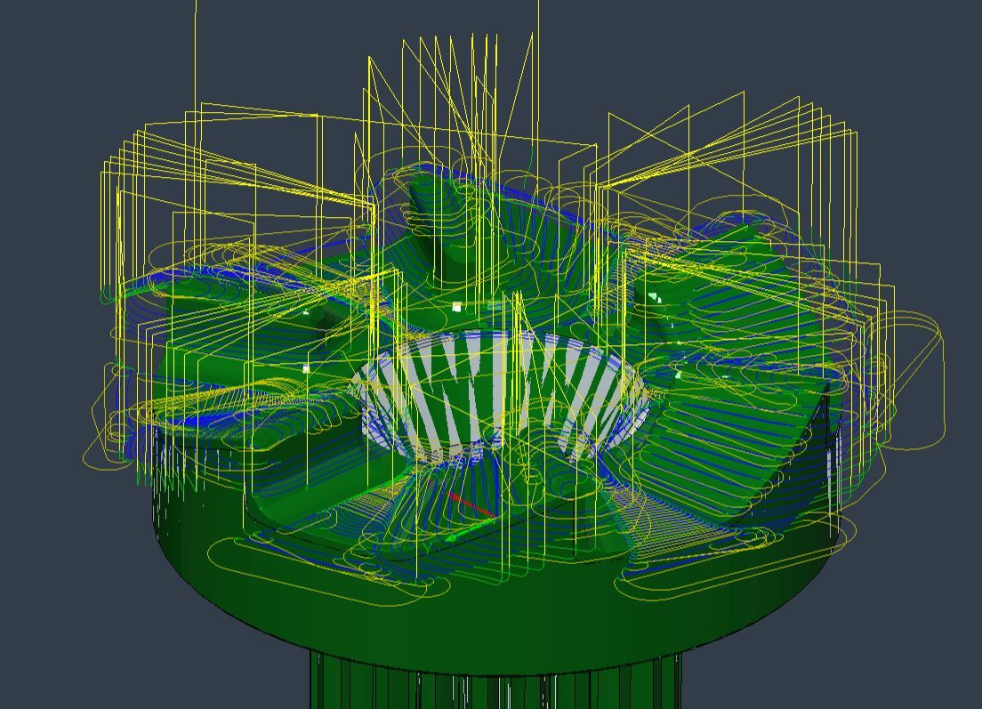
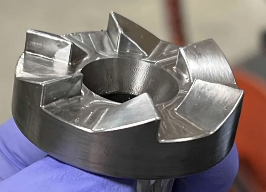
  • Previous designs opted for a “ramped” tooth configuration which was slightly lighter, but significantly more difficult to machine. The ramped teeth require 3D roughing and finishing toolpaths.
Complex toolpaths required to rough and finish the ramped tooth profile on last year’s design. The ramped tooth profile on last year’s design.
Complex toolpaths required to rough and finish the ramped tooth profile on last year’s design. The flat tooth design I went with this year decreases machining time by nearly 80%

After careful consideration I figured out what I was going to keep/change:

Minor design changes: Placement

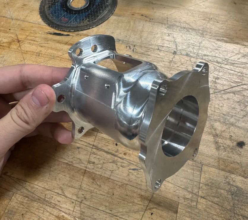
The input dog gear will slide inside of female splines on the gearbox output shaft. This reduces the total axial length of the assembly significantly and allows it to package nicely inside of existing material

OLD
OLD
NEW
NEW

Tooth Geometry

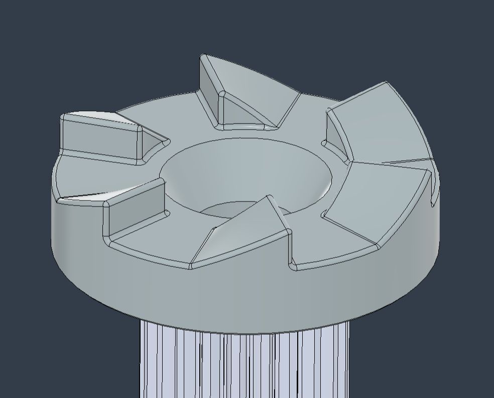
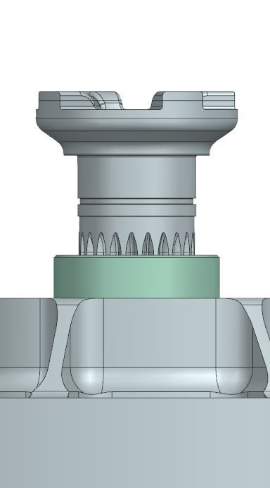
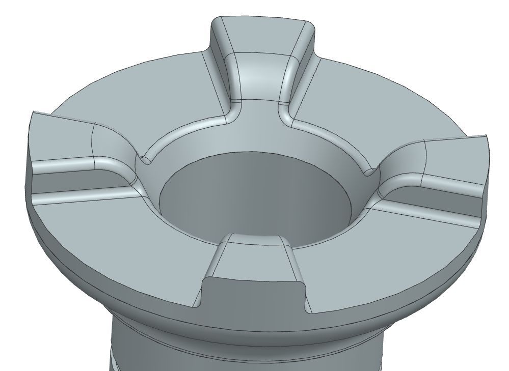
Teeth on both gears would shift from a ramp design to a flat design. This increases ease of machining and reduces the stress concentration at the tooth root.

OLD
NEW
NEW

Throwout fork and bearing packaging + identical componentry

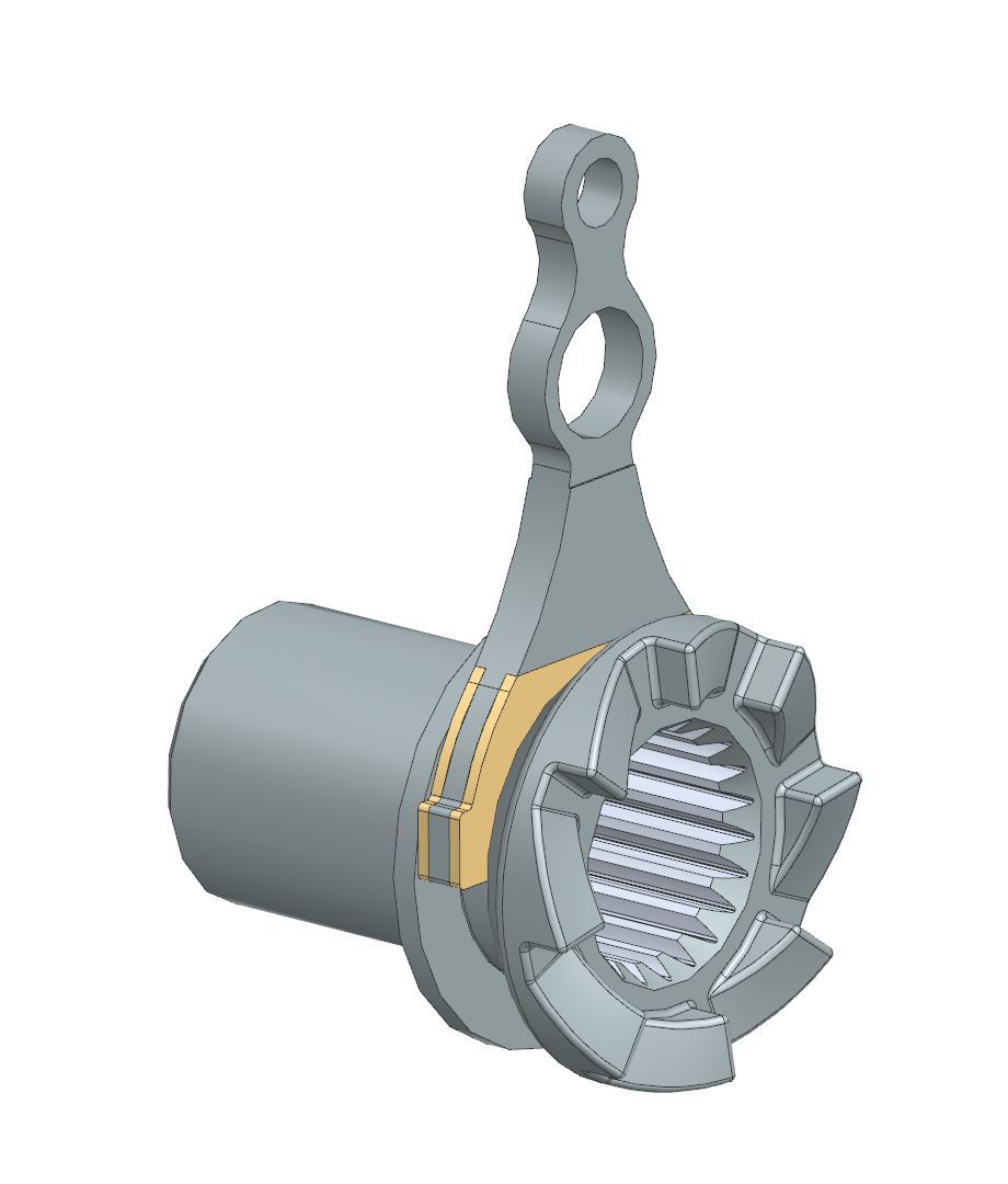
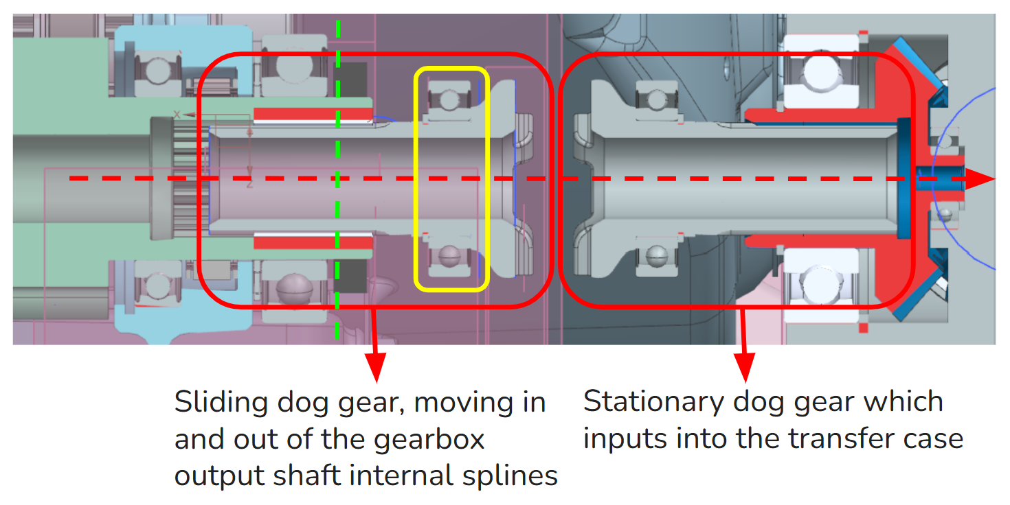
The stationary dog gear and the sliding dog gear are made into identical parts, but used differently.

Use the bearing that constrains the stationary dog gear inside of the housing as the connection between the throwout fork and the sliding dog gear. This prevents frictional wear from the throwout fork, which was a major issue with previous designs.

OLD
OLD
NEW
NEW

Carryover:

Material - AISI 4340 per AMS 6414

  • Low coefficient of friction on itself(important for sliding splines).
  • Thru-hardened to 34-36 HRC and 210 ksi.
  • Of the materials we have access to, it is most optimal for minimizing diameter and length of the gears while hitting FOS reqs.

Actuation Method - Push-pull cable

  • Electronically actuated dog would be more complicated and less consistent then the push pull cable. I did spec a cable with a more durable braided core, as opposed to the solid core from previous year.
SR26 4WD Actuation Dog Clutch

Major Change:

System level redesign of the rear inboard assembly.

  • Bevel gear reaction forces from the transfer case will be funneled through my structural housing into the gearbox, instead of directly into the frame through bolted connections
  • This significantly reduces overall frame weight and is a more efficient mass allotment then reinforcing frame members and routing them to create convenient mounting points for the transfer case.
SR26 4WD Actuation Dog Clutch

After figuring out what the general architecture of the system was going to be I moved into the preliminary calculation phase.

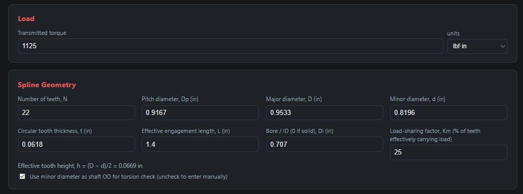
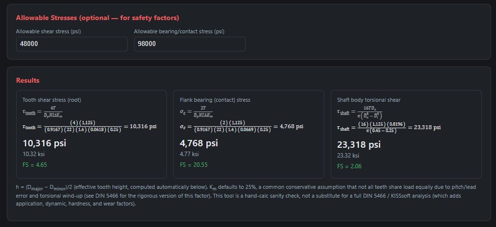
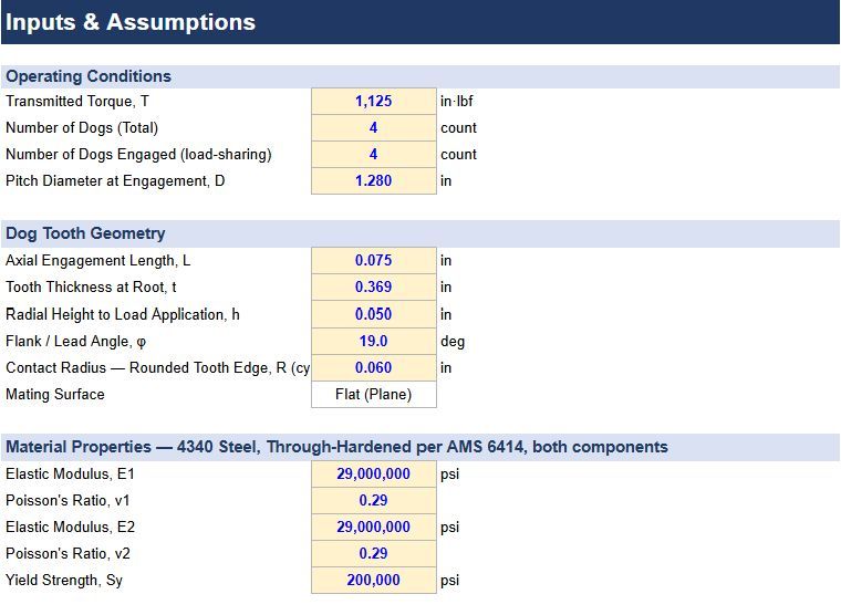
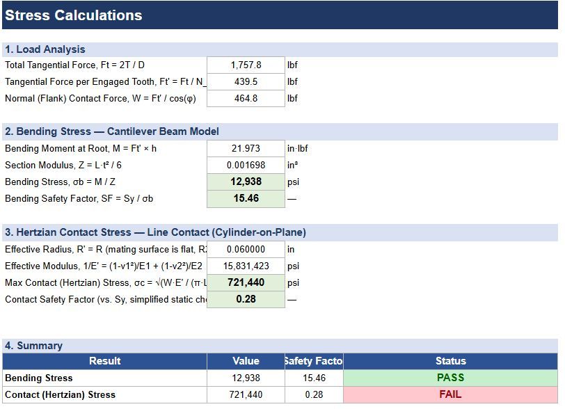
I determined spline length using equations from Dudley’s “When Splines Need Stress control”, calculated contact and bending stress using equations from Shigley’s Mechanical Engineering Design textbook, and performed bulk structural analysis in Ansys to prove out the housing redesign concept.

Initial spline sizing calculations given the known actuation distance Initial spline sizing calculations given the known actuation distance
Initial spline sizing calculations given the known actuation distance
Initial extremely simplified bending and contact stress calcs to size teeth and general profile Initial extremely simplified bending and contact stress calcs to size teeth and general profile
Initial extremely simplified bending and contact stress calcs to size teeth and general profile
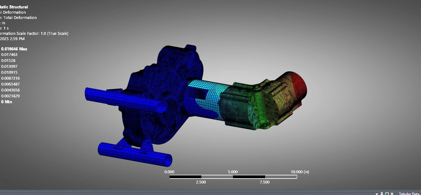
Static structural simulation to prove out the packaging concept.
Static structural simulation to prove out the packaging concept. I used a simplified tube and last year’s transfer case because those parts had yet to be redesigned. The cut taken out of the tube is to represent the hole necessary for the push-pull cable that actuates the mechanism.

After all of the initial sizing calculations, requirements, and system architecture were completed, I moved into the detailed design phase:

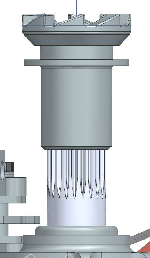
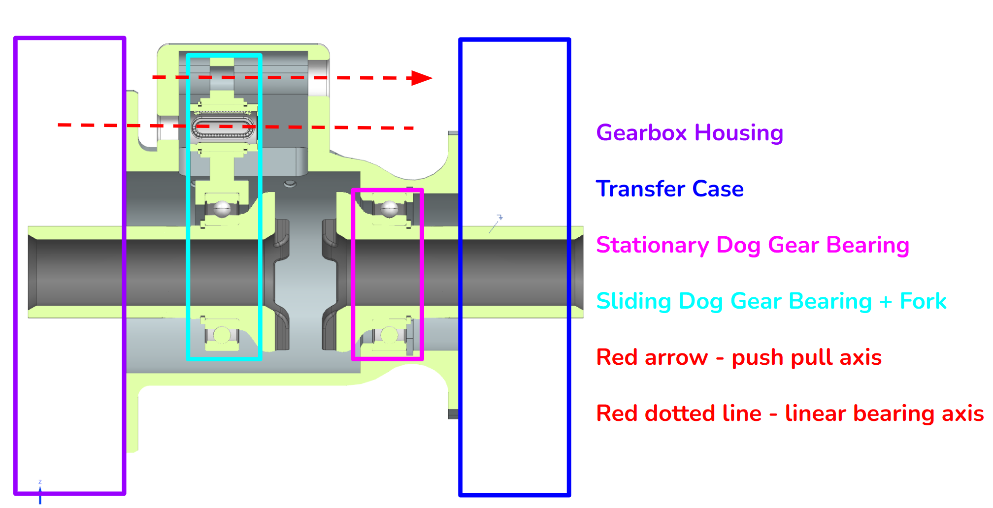
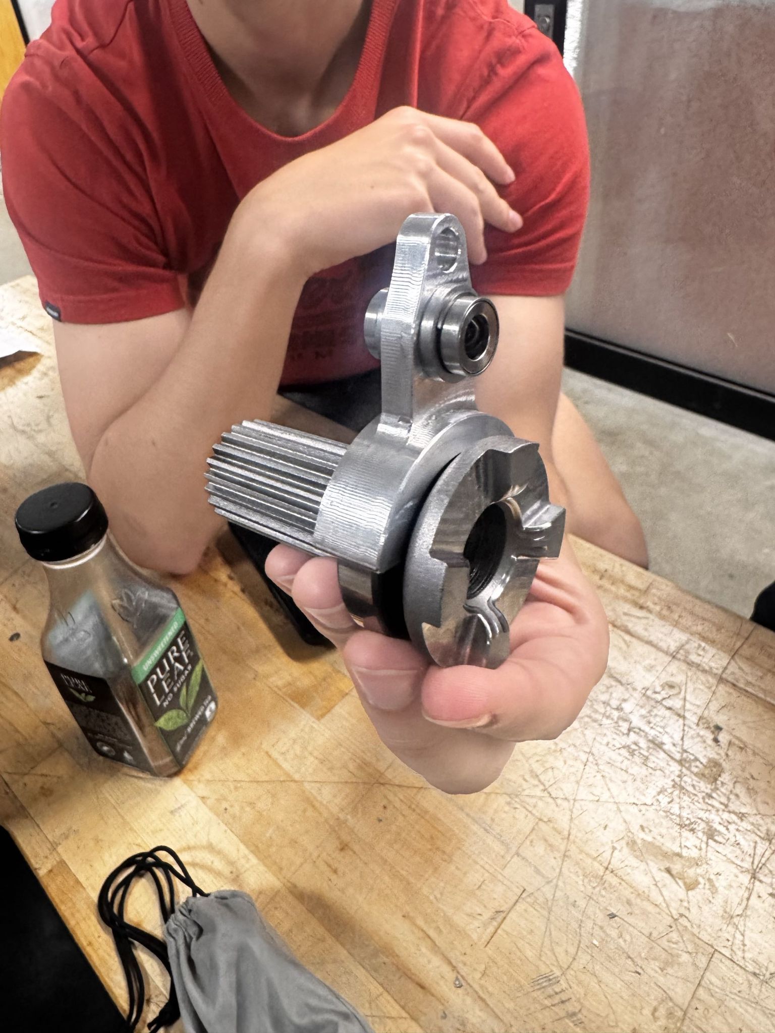
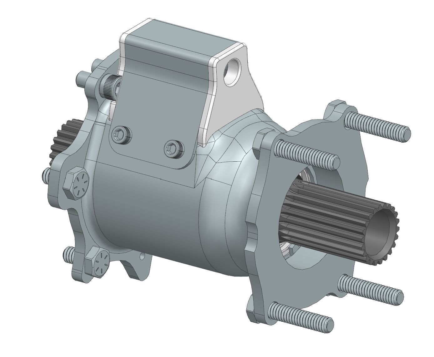
Note that the input and output dog gears are identical parts. On the input sliding dog gear, the bearing is used as the interface point between the rotating gear and the throwout fork. This prevents friction wear, which was a problem in previous years. The same bearing on the stationary gear is used to constrain it radially and take any of the dynamic loads that occur during engagements and disengagements. There is also a linear bearing on the fork which guides the engagement path.

System cross section

Detailed analysis at the part and assembly level:

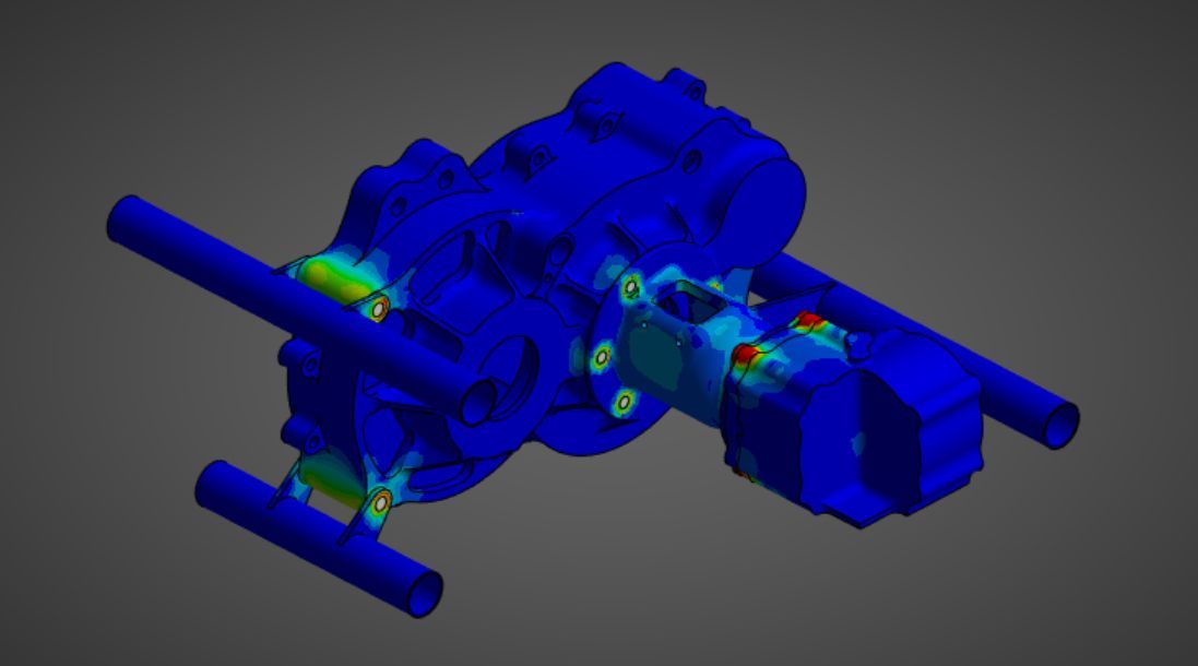
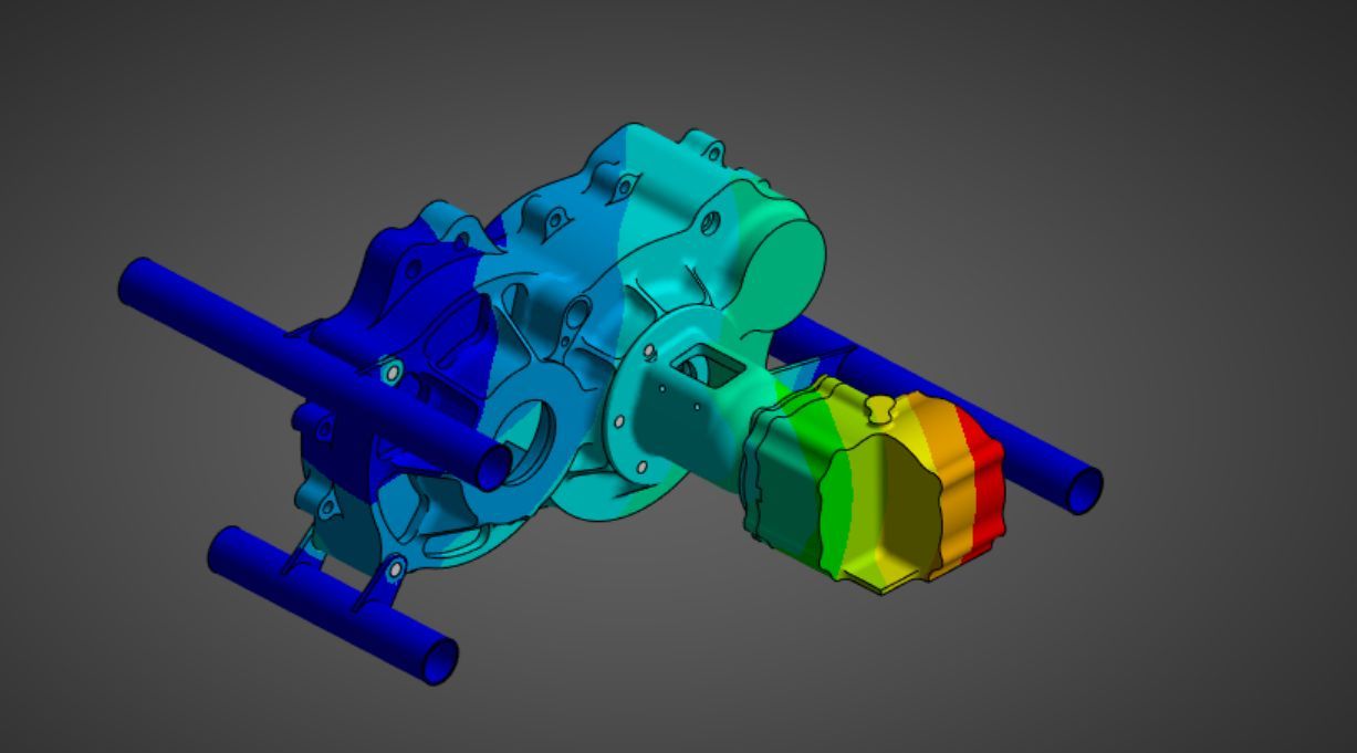
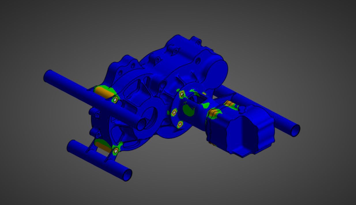
This simulation encompasses the entire rear drivetrain and frame. I wanted to investigate the effects of the bevel gear reaction forces + full drivetrain torque on the bulk structure of the rear inboard and how it would affect the interface of our rear transfer case with the propshaft system. I have the gearbox, rear frame structure, bevel gears, and a stiff body to ground spring to simulate the torsional stiffness of a locked propshaft/front driveline. What I found is that the stresses induced in the housings are minimal and the maximum deflection of the assembly was approximately 0.02 inches, which is well within the misalignment range of the crowned spline on our propshaft. The diameter and thickness of my structural housing was largely a function of the clutch component’s outer diameter and not a bending stiffness requirement. Despite being loaded by the bevel gear reaction forces, the housing was still able to reduce in weight from 0.53 lbs to 0.29 lbs. This is a much more effective mass usage than the previous housing which existed strictly to fulfill safety requirements.
Stress
Stress
Deformation
Deformation
FOS(green is <= 10)
FOS(green is <= 10)

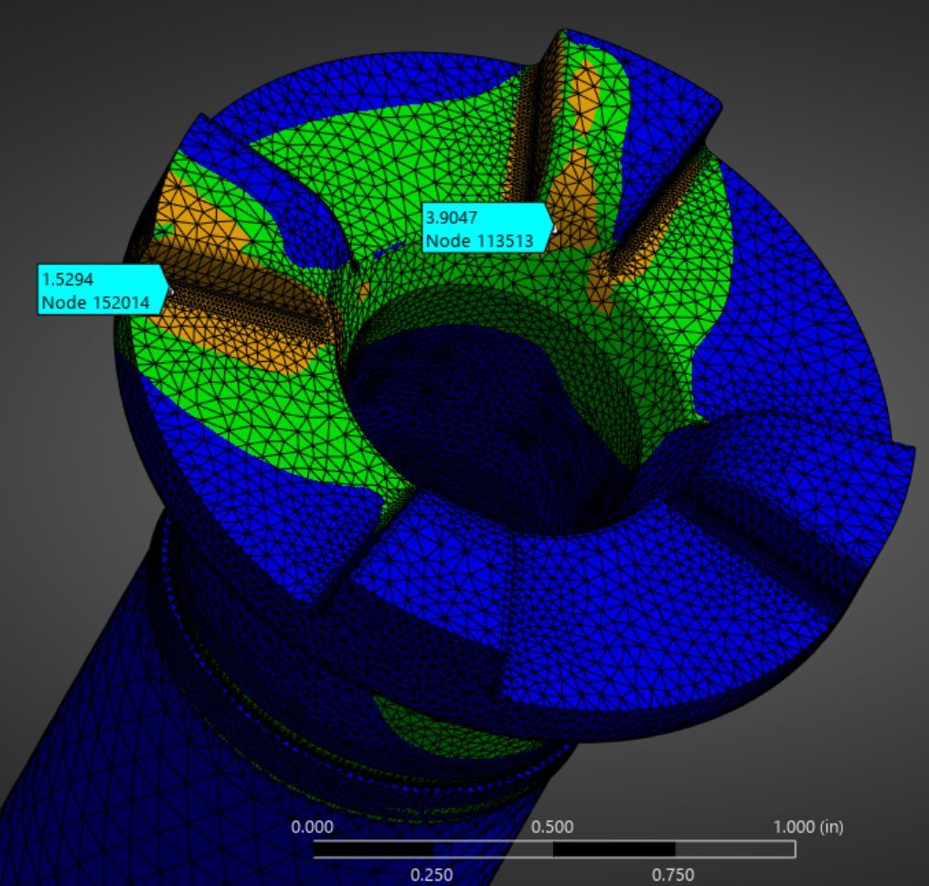
My tooth simulation was set up to simulate the absolute worst case engagement scenario. In this situation, max torque is being applied to the top half of only 2 of the teeth. This was derived from the maximum possible misalignment of the two gear’s axis and applying the moment along that misaligned axis. Even with the worst case situation, the minimum factor of safety is still above 1.5, which is the requirement for all drivetrain components. After further analysis, I was able to reduce the total weight of the component and assembly by over 20%, even with the 30% increase in torque from last year’s car. This is not even factoring in the enormous frame weight loss from the packaging redesign.
Dog Gear
Annotated gearbox housing, transfer case, stationary dog gear bearing, sliding dog gear bearing and fork, push-pull axis, and linear bearing axis

Manufactured parts gallery

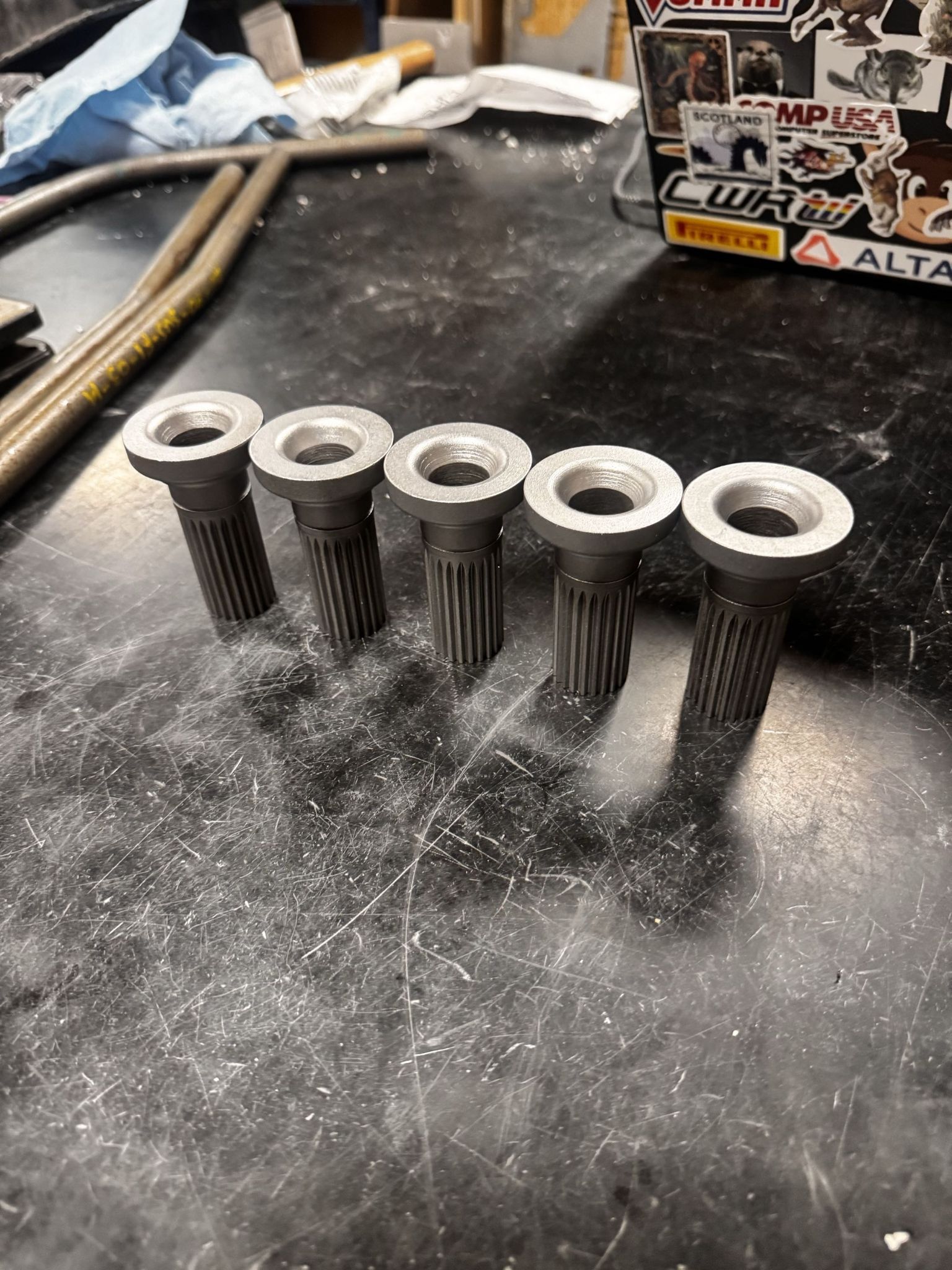
Hardened lathe blanks before tooth milling ops
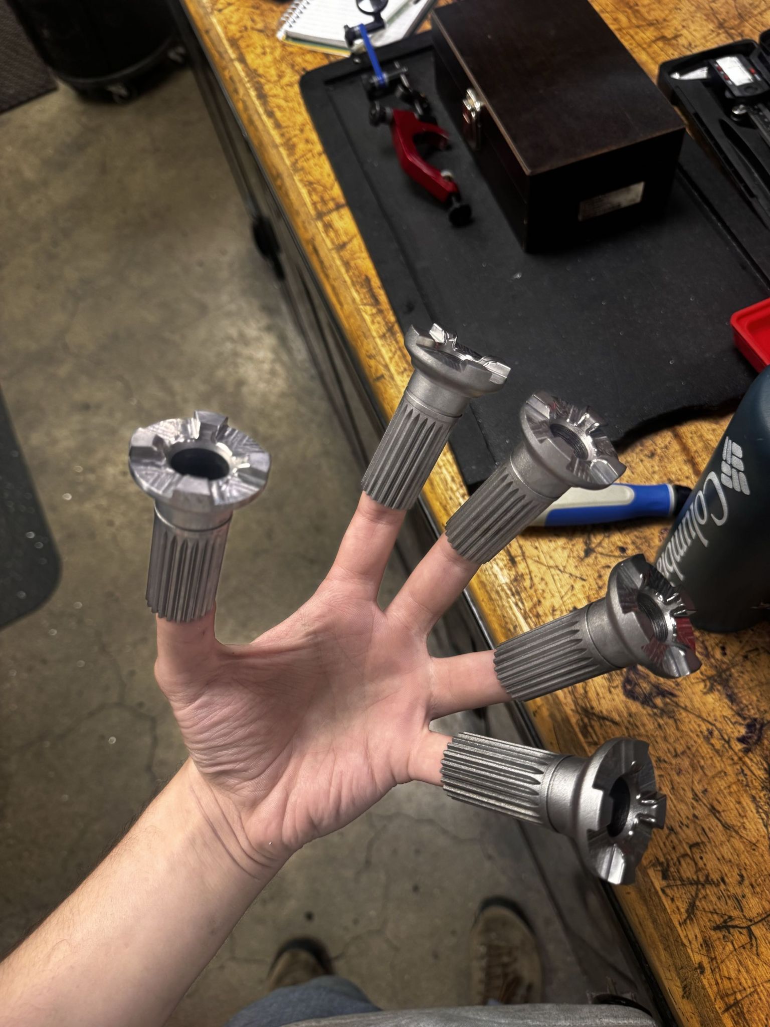
Dog gears fresh off the mill
Full part family
Full part family
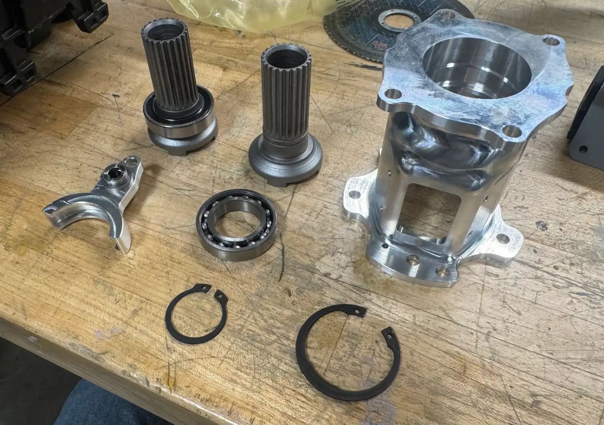
The Dawg Haus
The Dawg HausTM
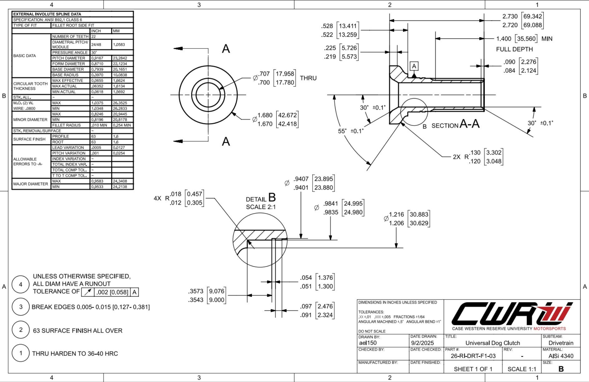
Drawing and spline table for lathe blank
Fully assembled sliding dog gear

End Results

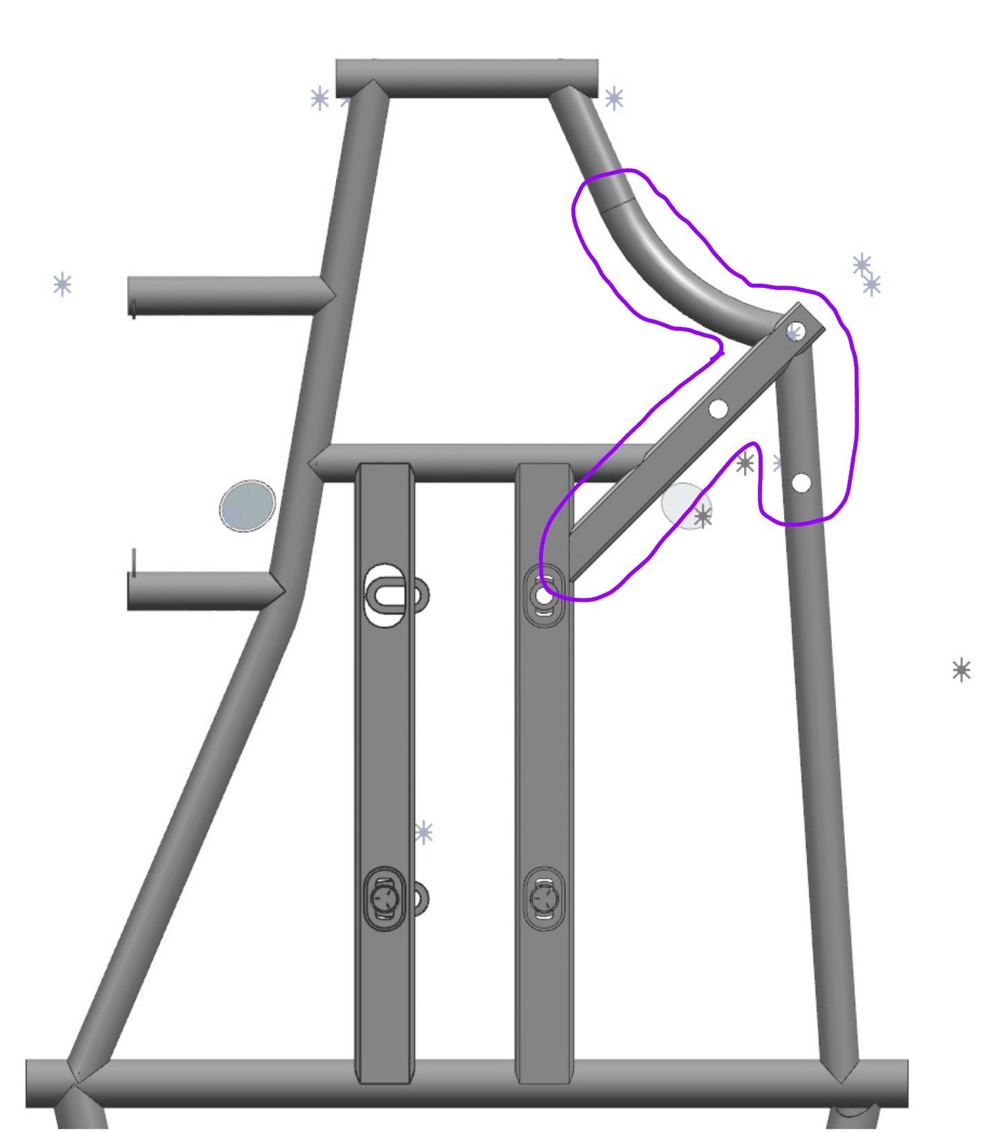
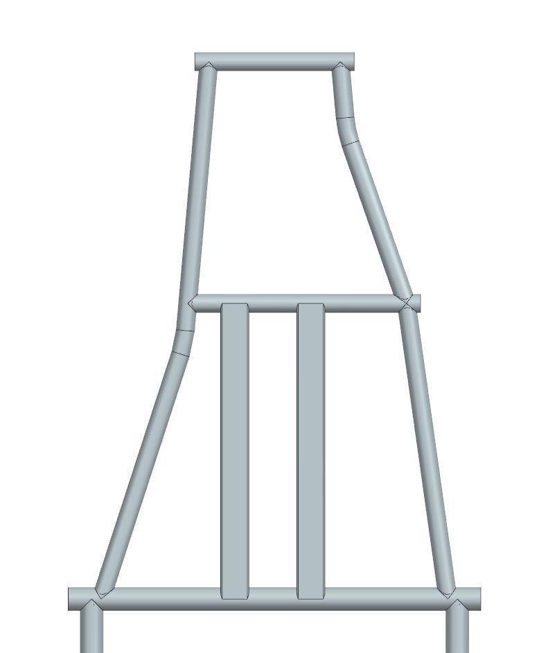
Removing the reinforced members highlighted in purple significantly reduced weight in the rear subframe area which allowed for an elongation of the wheelbase without dramatically increasing overall weight

OLD
OLD
NEW
NEW

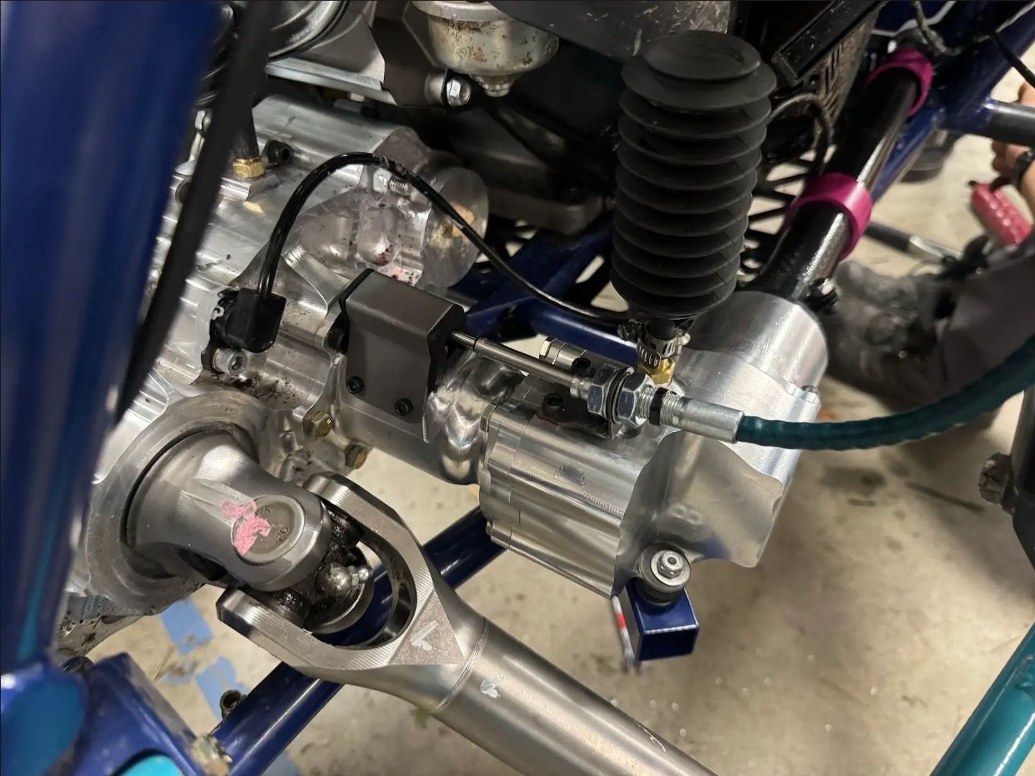
The assembly integrated into the rear inboard drivetrain of the car. Another benefit of this design was that the push pull cable and interior of the housing are accessible from the top and are able to be completely removed and serviced without taking out any other drivetrain components, which was a major issue with last year’s design.

SR26 4WD Actuation Dog Clutch

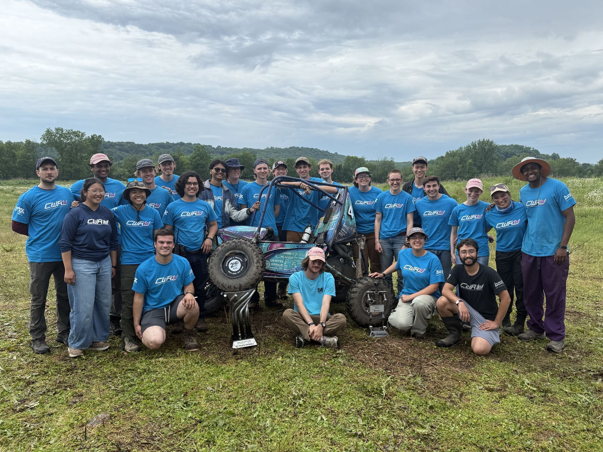
For the first time in our team’s history, our four wheel drive system worked for the entire duration of the period it was installed on the car. This allowed us to fulfill our vehicle level goals of being both consistent and nimble, and in doing so we were able to secure a 1st place overall finish at SAE New York.

1st place overall finish at SAE New York
1st place overall finish at SAE New York.